Longwave Radiation Balance
The earth and atmosphere are major sources and sinks of longwave radiation. Most surfaces on the earth are close to being perfect blackbodies (objects that absorb and re -emit all the radiation striking the object's surface) for the longwave part of the spectrum. The longwave radiation balance (Rlwbal) may be written as:
| ( 1 ) |
with ![]() and
and ![]() as the incoming (source=sky, clouds, etc.) and outgoing (source=earth's surfaces) longwave components, respectively. The wavelength of these components is usually in the range of 3 to 100 µm.
as the incoming (source=sky, clouds, etc.) and outgoing (source=earth's surfaces) longwave components, respectively. The wavelength of these components is usually in the range of 3 to 100 µm.
The energy flux, R, emitted by an object is related to its temperature by the Stefan-Boltzmann law:
| ( 2 ) |
where eobj is the emissivity of the object, s is the Stefan-Boltzmann constant (5.68 x 10⁻⁸ W m-2 K-4), and Tobj is the temperature of the object in K (Kelvin).
The total outgoing radiative flux (emitted plus reflected) may be written as:
| ( 3 ) |
where ![]() can be calculated from s TIRT4
can be calculated from s TIRT4
TIRT is the temperature (in K) of the object as measured with an infrared (IR) thermometer.
Using equation 3, the actual temperature of an object can be obtained by solving for Tobj if eobj , ![]() and
and ![]() are known:
are known:
| ( 4 ) |
2. Longwave Radiation Sensing
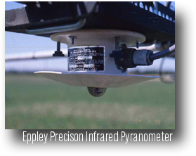
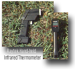
Thermal radiation measurements are based on the exchange of energy between hotter and cooler objects. Assuming that the infrared instrument is one of the objects, the instrument absorbs or emits energy if it is cooler or warmer than the object that is being sensed, respectively. An infrared instrument measures radiant energy beyond the sensitive range of the human eyes. All objects (with temperatures above -273o C) radiate this energy with an intensity relative to the temperature of the object. As an object becomes heated, the peak spectral response will move from the infrared to the visible spectrum, becoming "red hot". Longwave radiation can be measured with an Infrared Thermometer (IRT) (e.g., the Everest model 4000 IRT Transducer with multiplexer or an Everest Model 112 IRT) or a Pyrgeometer (e.g., Eppley Precision Infrared Radiometer (PIR)).
a) Infrared Thermometry
The detector of the infrared thermometer either absorbs or emits energy from the viewed object. The energy passing through the sensor's optics is either focused or dispersed from the IR-detector. The IR-detector converts the radiation to a proportional electrical signal that is the electrical analog of the IR radiation. In the case of the Everest model 4000, with a multiplexer or the Everest Model 112, the longwave radiation is converted to an analog signal proportional to the target temperature and a digital signal which controls the LCD display. If Everest Model 4000 is not used with a multiplexer, the company supplies algorithms to convert the radiation to a target temperature.
 IRT's are fast, simple, dependable and reliable with repeatable accuracy. Also, since there is no physical contact between the detector and target, the energy balance of the target is not altered during measurements.
It is possible to obtain the incoming and outgoing longwave radiation fluxes by measuring the ground (surface) and sky temperatures with an IRT and then applying the Stefan- Boltzmann law, via Equation 3.
The multiplexer, for the Everest model 4000IRT transducer, routes the electrical signal from the transducer to a preamplifier in which the signal is linearized and converted to an equivalent digital signal which excites the liquid crystal digital display on the multiplexer. The analog signal is still available to be read by the data logging system.
 If a multiplexer is used, a 110 volt AC or 12 volt DC power supply is needed. (Click on Image to see multiplexer image) If a multiplexer is not used, a positive unregulated filtered DC voltage source between 5 and 10 volts and a regulated -2.367 volt DC voltage source are needed.
b) Eppley Precision Infrared Radiometer (pyrgeometer) - PIR
A PIR is used to measure, hemispherically, the exchange of longwave radiation between a horizontal blackened surface (the detector) and the target viewed (i.e. the sky or the ground). The PIR has the same circular multi- junction thermopile (detector) as the Eppley PSP which is used as a method of transducing the longwave radiation flux into a electrical response (Figure 1). The inner silicon dome is coated with a vacuum-deposited interference filter. Radiation at wavelengths from 0.3-0.4 µm to approximately 50 µm is transmitted into the sensor. The amount of radiation in the visible spectrum 0.3-4.0 µm is not significant; absorption and re-emission effects are small and have been compensated for in the calibration.Figure 1 - Sketch of the Eppley pyrgeometer (not to scale) and schematic of the pyrgeometer curcuit. Typical resistance values are RT = 10.0 KW at 25oC, R1 = 35.8 KW, R2=9.97 KW and R0 = 35.4 W.
The PIR is designed to compensate for two errors in measurement: 1) temperature differences between the instrument dome and the actual detector and 2) the temperature difference between the detector and the actual object being sensed. To correct the first error, thermistors have been attached to the inner dome and to the detector to measure the temperatures of each object (Albrecht and Cox, 1977). The PIR also has a thermistor-battery-resistance circuit that can be used to provide an output to compensated for detector temperature. The battery is 1.35 Volts. However, the output from this circuit can be affected by voltage fluctuations. As an alternative the direct output from the thermopile and the temperature from the thermistor embedded in the thermopile can be used. Basically, three outputs are needed to calculate the longwave radiation:
- thermopile or the thermistor-battery-resistance circuit output
- dome thermistor output
- thermopile thermistor output.
The thermopile output is preferred over the battery circuit because of battery voltage fluctuations. The thermistors need to be excited with a voltage source (in this case, from the data logger), thus the output is proportional to temperature.
Click here for calculating flux from the PIR.
Click here for example of data from the pyrgeometer.
- Eppley Laboratory, Inc.
12 Sheffield Ave.
Newport, RI 02840
(401) 847-1020
http://www.eppleylab.com/ - Everest Interscience, Inc.
P.O. Box 3640
Fullerton, CA 92634-3640
(714) 992-4461
Calibration
a) IRTs should be calibrated before the beginning and the end of an experiment. The IRT is calibrated against a variable black-body source set at a range of temperatures under a range of ambient temperatures. An environmental chamber at different temperatures (e.g., 10o, 20o, 30oC) can be used for calibration. A linear relation between the measured IRT value and the known source is used to correct all measured values.
b) Eppley recommends that the PIR be recalibrated yearly. As with the IRT the PIR is calibrated against a calibrated black-body of known temperature at a range of ambient conditions. Since the PIR receives longwave radiation from all directions from the hemisphere, a blackbody cavity is required. A water bath in an environmentally controlled chamber can be used for this purpose but it is recommended that the instrument be returned to the manufacturer for calibration due to the precision measurements required.
Installation
a) Since an IRT can only respond to what is in the field of view (FOV) of the sensor, the target being measured must completely fill the instrument's FOV, in order to give reliable readings. The Everest IRT model 4000 and model 112 have a 15o FOV and spectral band passes of 8-14 µm. Different FOVs are available from Everest for the Model 112. If the measurement is to encompass a large field area and not a specific small plot area the instrument should be directed at a 45 degree angle from horizontal facing north. The instrument will see mostly sunlight objects and near solar noon will measure the "hot spot" of the canopy (i.e., the instrument will view mostly sunlit portions of the leaves and soil.)
b) The site for measurements of incoming upper-hemispheric longwave radiation with an upward-looking PIR, should be free from any significant obstructions above the plane of the sensing element, and at the same time, should be readily accessible. In the case of a downward-looking PIR for the measurement of outgoing longwave radiation fluxes (emitted and reflected) in general field application the pyrgeometer should be mounted at least 1 to 2 meters above the top of the surface being viewed. In both cases, the instrument should be mounted horizontally. The lead wires should face north (when conducting experiments in the northern hemisphere), for both mounting orientations, to reduce any errors from heat conduction along the lead wires.
Operation and Maintenance
Several steps should be followed to ensure the collection of reliable data:
- Periodic calibration of instruments; for the IRT a portable blackbody source can be used.
- Periodic inspection of instruments
- Keep instruments clean and dry
- Mount instruments on stable platforms
- Replace the silica gel drying agent in the desiccant as frequently as necessary (color of desiccant is a measure for its drying power).
- Replace dome when calibration verifications are suspect, but never touch the vacuum- deposited interference filter on the internal surface of the hemisphere. DO THIS VERY CAREFULLY.
References
Albrecht, B. and S.K. Cox. 1977. Procedures for improving pyrgeometer performance, J. of Appl. Meteorol., 16:188-197.